The Infinite Loop

Tales from a lean programmer.


2 Comments

Test-and-set spinlocks

In my previous blog post I wrote about the most important properties of spinlocks and why they matter. This time I’ll present the first out of three concrete spinlock implementations in C++11 for x86 processors. I’m assuming that you’ve read the first post. You can find all source code in this Github repository.

Introduction

The Test-And-Set (TAS) Lock is the simplest possible spinlock implementation. It uses a single shared memory location for synchronization, which indicates if the lock is taken or not. The memory location is updated using a test-and-set (TAS) operation. TAS atomically writes to the memory location and returns its old value in a single indivisible step. Actually, the name test-and-set is a little misleading, because the caller is responsible for testing if the operation has succeeded or not. The TAS Lock is not fair as it doesn’t guarantee FIFO ordering amongst the threads competing for the lock.

In C++11 std::atomic_bool::exchange() can be used to perform a TAS operation on an std::atomic_bool synchronization variable. On x86 CPUs std::atomic::exchange() is turned into the LOCK XCHG instruction (side note: the LOCK prefix is implicit and not strictly required, because there’s no non-atomic version of XCHG). The following code implements the described TAS Lock.

class TasSpinLock
{
public:
    ALWAYS_INLINE void Enter()
    {
        // atomic_bool::exchange() returns previous value of Locked
        while (Locked.exchange(true, std::memory_order_acquire) == true);
    }

    ALWAYS_INLINE void Leave()
    {
        Locked.store(false, std::memory_order_release);
    }

private:
    alignas(CACHELINE_SIZE) std::atomic_bool Locked = {false};
};

static_assert(sizeof(TasSpinLock) == CACHELINE_SIZE, "");

The TasSpinLock::Locked flag is cache line size padded using alignas to prevent false sharing. You can remove the padding, e.g. in memory-limited environments, when false sharing is not an issue.

The test-and-test-and-set optimization

While the TAS Lock is extremely easy to implement, its scalability is very bad. Already with just a few threads competing for the lock, the amount of required cache line invalidations to acquire/release the lock quickly degrades performance. The problem is two-fold.

  1. std::atomic_bool::exchange() always invalidates the cache line Locked resides in, regardless of whether it succeeded in updating Locked or not.
  2. When the spinlock is released, all waiting threads simultaneously try to acquire it. This is sometimes referred to as Thundering Herd problem. Acquiring the lock means first invalidating the cache line copy of all threads waiting for the lock and then reading the valid cache line copy from the core which released the lock. With t threads this results in O(t) memory bus transactions.

The latter issue is inherent to TAS Locks, because just a single synchronization variable is used and shared between all threads. However, the first issue can be fixed by testing if the lock is free before calling exchange(). First testing if the lock is free only loads the synchronization variable and therefore doesn’t cause a cache line invalidation. This spinlock variant is called Test-And-Test-And-Set (TTAS) Lock. The improved Enter() method looks like this:

ALWAYS_INLINE void TTasSpinLock::Enter()
{
    do
        WaitUntilLockIsFree();
    while (Locked.exchange(true, std::memory_order_acquire) == true);
}

ALWAYS_INLINE void TTasSpinLock::WaitUntilLockIsFree() const
{
    while (Locked.load(std::memory_order_relaxed) == true);
}

Exponential back-off

The TTAS Lock successfully reduces the amount of cache line invalidations occurring while the lock is trying to be acquired. However, as soon as the lock is released, again all threads try to update the Locked flag. If a thread sees that the lock is free, but fails acquiring it subsequently because some other thread was faster, the lock is most probably under high contention. In this situation it can help to wait for a short time to let other threads finish before trying to enter the critical section (CS) again.

Waiting a short time without trying to acquire the lock reduces the number of threads simultaneously competing for the lock. The larger the number of unsuccessful retries, the higher the lock contention and the longer the thread should back-off. Experiments have shown that a good strategy is to back-off exponentially; similar to the congestion avoidance mechanism used in the Ethernet protocol. To avoid threads running in lock step the initial wait time is randomized.

ALWAYS_INLINE static void BackoffExp(size_t &curMaxIters)
{
    assert(curMaxIters > 0);

    thread_local std::uniform_int_distribution<size_t> dist;
    thread_local std::minstd_rand gen(std::random_device{}());
    const size_t spinIters = dist(gen, decltype(dist)::param_type{0, curMaxIters});

    curMaxIters = std::min(2*curMaxIters, MAX_BACKOFF_ITERS);
    for (volatile size_t i=0; i<spinIters; i++); // Avoid being optimized out!
}

ALWAYS_INLINE void ExpBoTTasSpinLock::Enter()
{
    size_t curMaxIters = MIN_BACKOFF_ITERS;

    while (true)
    {
        // Not strictly required but doesn't hurt
        WaitUntilLockIsFree();

        if (Locked.exchange(true, std::memory_order_acquire) == true)
            BackoffExp(curMaxIters); // Couldn't acquire lock => back-off
        else
            break; // Acquired lock => done
    }
}

The downside of waiting is that it renders the lock even unfairer than it is already. Threads that have been attempting to acquire the lock longest are also backing-off longest. Consequently, newly arriving threads have a higher chance to acquire the lock than older threads. On top of that threads might back-off for too long, causing the CS to be underutilized. Furthermore, there are unfortunately no single best values for MIN_BACKOFF_ITERS and MAX_BACKOFF_ITERS. Optimally, they’re determined experimentally depending on the workload (contention, size of CS).

Pausing and sleeping

There are two more improvements we can do. First, according to the Intel Architectures Optimization Reference Manual, adding a PAUSE instruction to the body of all spin loops improves performance on Pentium 4 CPUs and later. The PAUSE instruction provides a hint to the CPU that the code being executed is a spin-wait loop. PAUSE is backwards compatible and turns into a NOP instruction on older CPUs. There are three reasons why using PAUSE improves performance:

  • It avoids memory order violations which result in expensive pipeline flushes, because the CPU doesn’t go ahead to fill its pipeline with speculatively executed load and compare instructions.
  • It gives the other hardware thread time to execute on simultaneous multi-threading (SMT) processors (e.g. Intel’s Hyper Threading).
  • It adds a slight delay to the spin loop, which synchronizes it with the system’s memory bus frequency. This frequency is typically much lower than the frequency of the CPU, which in turn reduces power consumption considerably.

The second improvement is to stop spinning, put the thread to sleep and reschedule if the the lock doesn’t become available after some time. The important bit here is to not yield (sched_yield() on Linux, SwitchToThread() on Windows, or more generally std::this_thread::yield() in C++11), but to explicitly put the thread to sleep for a short period of time. This ensures that the thread is really paused for some time and isn’t immediately run again by the scheduler if there’s no other thread available in the scheduler’s run queue. This is especially important on SMT processors where every two logical cores share most of the execution units. Only when the thread is really sleeping the other logical core can fully make use of the shared execution units. The following TTAS Lock implementation uses the PAUSE instruction and sleeps for 500us if the lock isn’t released within MAX_WAIT_ITERS iterations. There’s no single best value for MAX_WAIT_ITERS. Ideally, it’s chosen experimentally like the MIN_BACKOFF_ITERS and MAX_BACKOFF_ITERS constants from before.

ALWAYS_INLINE static void CpuRelax()
{
#if (COMPILER == MVCC)
    _mm_pause();
#elif (COMPILER == GCC || COMPILER == LLVM)
    asm("pause");
#endif
}

ALWAYS_INLINE static void YieldSleep()
{
    // Don't yield but sleep to ensure that the thread is not
    // immediately run again in case scheduler's run queue is empty
    using namespace std::chrono;
    std::this_thread::sleep_for(500us);
}

ALWAYS_INLINE static void BackoffExp(size_t &curMaxIters)
{
    ... Unchanged code not repeated, look above ...

    for (size_t i=0; i<spinIters; i++)
        CpuRelax();
}

ALWAYS_INLINE void ExpBoRelaxTTasSpinLock::WaitUntilLockIsFree() const
{
    size_t numIters = 0;

    while (Locked.load(std::memory_order_relaxed))
    {
        if (numIters < MAX_WAIT_ITERS)
        {
            CpuRelax();
            numIters++;
        }
        else
            YieldSleep();
    }
}

Performance comparison

The benchmark used to compare the different TAS Lock variants is extremely simple and should be taken with a grain of salt. It launches t threads, each competing for the lock and incrementing a global atomic counter inside the CS. This causes high lock contention, because all threads are trying to enter the lock at the same time. Though, it’s important to keep in mind that due to the lock’s lack of fairness, it’s entirely possible that the same thread acquires the lock multiple times in a row. I ran the benchmark on a dual socket NUMA system with two Intel Xeon E5-2630 v2 CPUs with 2.60 GHz. The CPUs support Hyper Threading which gives a total of 12 physical and 24 logical cores. The benchmark results are shown below.

TAS Lock benchmark results

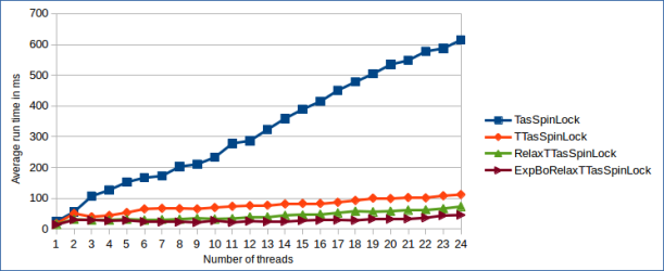
The most interesting finding is that the amount of lock reacquisitions is a lot higher than I anticipated. This can be derived from the fact that all TTAS-based locks scale almost linearly, where typically the observed drop in performance for TAS-based locks is exponential. Large numbers of lock reacquisitions by the same thread reduces the amount of cache line invalidations and increases throughput. At the same time the latency of all other threads goes up, because they’re granted the lock later.

The TasSpinLock scales so much worse, even though lock reacquisiton happens, because while spinning the TAS operation causes cache line invalidations also if it doesn’t succeed in acquiring the lock. By looking at the difference between the TasSpinLock and the other TTAS-based versions, it’s highly visible how big the influence of cache line invalidations is on the lock’s performance.

Wrapup

The exponential back-off TTAS Lock tends to perform fairly well as long as the number of competing threads is low or lock reacquisitions boost throughput while increasing latency. It’s especially useful when it’s not known a priori that the number of competing threads is bounded by the number of cores in the system (in that case better scaling spinlock variants perform really badly as we’ll see in the next post). Beyond that, without padding the TTAS Lock just needs a single byte. The compact representation is useful in extremely memory-constrained environments or applications that require vast amounts of spinlocks; e.g. for fine-grained locking of lots of small pieces of data.


1 Comment

Important properties of spinlocks

Typically, when a thread tries to acquire an already locked mutex it will go to sleep and give up its time slice, allowing another thread to run immediately instead. If the duration for which the mutex is held is extremely short, the time for putting the waiting thread to sleep and waking it up again to retry can easily be longer. In such cases spinlocks can be used to increase performance, by continuously trying to acquire the lock without sleeping. Side note: Obviously, it makes no sense to use spinlocks in systems with a single CPU core. Polling for the spinlock to become available would only prevent the single available CPU core from running the other thread to release the lock.

To deep dive into the multitude of spinlock implementations, it’s crucial to understand what their key characteristics are. Generally, spinlocks can be grouped into fair and unfair as well as scalable and unscalable implementations. In addition, we look at the spinlock’s memory footprint. The three properties are discussed in more detail in the rest of this post.

For all the nitty-gritty architectural details of concrete C++11 spinlock implementations read the upcoming blog posts about Test-And-Set (TAS) Locks, Ticket Locks and MCS Locks. I’ll upload the source code to this Github repository.

Scalability

Existing spinlock variants have very different performance characteristics under contention. A lock is said to be contented when there are multiple threads concurrently trying to acquire the lock while it’s taken. The performance of unscalable spinlock implementations degrades as the number of threads trying to acquire the lock concurrently goes up. The performance of simple Ticket or TAS Locks for example drops exponentially with increasing numbers of threads. In contrast, scalable spinlock implementations – like e.g. the MCS Lock – exhibit no degradation in performance even for large numbers of threads. The scalability graph of the optimal spinlock vs the Ticket Lock is depicted in the graph below.

Scalability of optimal spinlock

Crucial for the scalability of spinlocks is the amount of cache line invalidations which take place when the lock is acquired and released. Cache line invalidations take place when e.g. a thread modifies a synchronization variable while leaving a critical section (CS) on which other threads are polling at the same time. Suddenly, cache line copies stored in caches of other CPU cores are not valid anymore. Accordingly, these cache lines must be invalidated and reobtained from the CPU core’s cache which modified it. Thus, the number of cache line invalidations which occur when the spinlock is acquired/released is often used as a metric to compare spinlock implementations with each other. Usually, scalable spinlocks require O(1) many cache line invalidations to acquire/release the lock, while unscalable spinlocks require O(#threads) many.

Advanced scalable spinlock implementations may not only take the total number of CPU cores in a system into account, but also the details of the underlying cache coherency mechanism. For example in systems with multiple CPUs and non-uniform memory access times (NUMA), inter-core communication costs may vary greatly. For example in a NUMA system with multiple multi-core CPUs it’s entirely possible to pass a lock to another core within in the same CPU in less time than to a core of another CPU.

Fairness

Fair spinlocks guarantee that the same thread may never reacquire the lock if there are other threads trying to acquire the same lock at the same time. Fair spinlocks maintain a first-in-first-out (FIFO) order among the threads attempting to acquire the lock.

Often, unfair spinlocks trade latency for throughput, while fair spinlocks trade throughput for latency. Consider the following example. Let’s say we’re running t threads each performing n/t loop iterations in which they try to enter a CS. When using an unfair spinlock, in the worst case (at least in theory) every thread could enter the CS n/t times in a row instead of alternating with lock acquisition between threads. In certain scenarios this can boost throughput considerably, because the number of expensive cache line invalidations is reduced. However, the time until any other thread may enter the CS rises. In theory this can lead to starvation. In practice the cache coherency protocol should ensure that no starvation occurs.

Typically, the performance of fair spinlocks drops extremely when the number of threads competing for the same lock is greater than the number of CPU cores in the system. The reason for this is that the thread which is next in the sequence to acquire the lock might be sleeping. In contrast to unfair spinlocks, during the time the next thread is sleeping no other thread can acquire the lock because of the strict acquisition order guaranteed by the fair lock. This property is sometimes referred to as preemption intolerance.

Memory footprint

Generally, the required memory to store l spinlocks can depend on the number of threads t which are using the lock. While some spinlock implementations require only constant memory for t threads, other’s memory footprint scales linearly with the number of threads. The amount of needed memory to store a spinlock mostly doesn’t matter, because the memory footprint for the majority of locks is in the order of a few dozen bytes per thread. Mostly it’s a multiple of the CPU’s cache line size to account for false sharing. However, there are cases where the memory footprint plays an important role. Examples are extremely memory-constrained environments or applications that require vast amounts of spinlocks e.g. for fine-grained locking of lots of small pieces of data.


16 Comments

An overview of direct memory access

Introduction

Direct memory access (DMA) is conceptually easy, but without experience in hardware design or driver development it can be cumbersome to understand. In this blog post I will explain what DMA is and how it evolved during the last decades. My goal is to make it comprehensible especially for people without experience in hardware design or driver development.

DMA allows computer devices of certain hardware sub-systems to directly access system memory and other device’s memory independently of the CPU. This enables the CPU to keep on working concurrently on other task while long lasting memory operations take place; considerably boosting overall system performance. DMA is used by different hardware like graphics cards, sound cards, network cards and disk drive controllers. DMA is rather a concept than a specific technology. There is no specification which describes in detail how DMA transfers work. Even on the contrary, the concept of directly accessing memory without CPU interaction is employed in many different hardware sub-systems in today’s computers. The most typical application is communicating with peripheral devices plugged into a bus system like ATA, SATA, PCI or PCI Express. Beyond that, DMA transfers are used for intra-core communication in micro processors and even to copy data from the memory of one computer into the memory of another computer over the network via remote DMA (don’t mix up this technology with NVIDIA’s new GPUDirect RDMA feature).

To give a concrete example, imagine you’re playing an open world computer game which loads new game assets on demand from your hard disk. Large amounts of game data must be copied over from hard disk into system RAM. Without DMA the CPU would be actively involved in each and every memory transfer operation. Consequently, less computing time would be left for other game play related tasks like AI or physics. In times of multi-core processors this seems less like a problem. However, as data volumes and work load sizes are ever growing, off-loading large memory transfer operations from the CPU is also today absolutely essential in order to achieve high system performance.

How DMA evolved over time

In my experience many software people think that DMA nowadays still works as it did in the old days. I guess this is because it’s the more intuitive way to think about DMA. Back then, extension devices did not actively take part in DMA transfers, but there was a DMA controller (e.g. the Intel 8237, first used in the IBM PC in 1981) which enabled DMA transfers between system memory and device I/O over the good old Industrial Standard Architecture (ISA) bus. The DMA controller could be programmed by the CPU to perform a number of memory transfers on behalf of the CPU. This way of accomplishing DMA transfers is also known as third party DMA. At that time the system bus was identical to the ISA expansion bus. To account for reduced bus performance in situations where CPU and DMA controller needed to access the bus simultaneously, different DMA modes (cycle stealing, transparent and burst) could be used. When the first IBM AT clones came out, the expansion bus got physically separated from the system bus using an ISA bridge. This was necessary because the AT clones had CPUs running at higher frequencies than the expansion bus. In the figure below the single bus and the separated bus architectures are depicted.

Single vs separate bus architecture

With the introduction of the conventional Peripheral Component Interface (PCI) bus architecture in 1992, the DMA controller became obsolete because of a technique called bus mastering, or first party DMA. PCI DMA transfers were implemented by allowing only one device at a time to access the bus. This device is called the bus master. While the bus master holds the bus it can perform memory transfers without CPU interaction. The fundamental difference between bus mastering and the use of a DMA controller is that DMA compatible devices must contain a DMA engine driving the memory transfers. As multiple PCI devices can master the bus, an arbitration scheme is required to avoid that more than one device drives the bus simultaneously. The advantage of bus mastering is a significant latency reduction because communication with the third party DMA controller is avoided. Additionally, each device’s DMA engine can be specifically optimized for the sort of DMA transfers it performs.

PCI architecture

Today’s computers don’t contain DMA controllers anymore. If they do so, it’s only to support legacy buses like e.g. ISA, often by simulating an ISA interface using a Low Pin Count (LPC) bus bridge. In 2004 the PCI successor and latest peripheral computer bus system PCI Express (PCIe) was introduced. PCIe turned the conventional PCI bus from a true bus architecture, with several devices physically sharing the same bus, into a serial, packet-switched, point-to-point architecture; very similar to how packet-switched networks function. PCIe connects each device with a dedicated, bi-directional link to a PCIe switch. As a result, PCIe supports full duplex DMA transfers of multiple devices at the same time. All arbitration logic is replaced by the packet routing logic implemented in the PCIe switches. While PCIe is entirely different to PCI on the hardware level, PCIe preserves backwards compatibility with PCI on the driver level. Newer PCIe devices can be detected and used by PCI drivers without explicit support for the PCIe standard. Though, the new PCIe features cannot be used of course.

PCIe architecture

DMA from a driver developer’s perspective

Now you know what DMA is and how it fits into a computer’s hardware architecture. So let’s see how DMA can be used in practice to speed up data heavy tasks. Since the dawn of DMA the driver (software) must prepare any peripheral DMA transfers, because only the operating system (OS) has full control over the memory system (we see later why this is important), the file system and the user-space processes. In the first step, the driver determines the source and destination memory addresses for the transfer. Next, the driver programs the hardware to perform the DMA transfer. The major difference between PCI/PCIe DMA and legacy ISA DMA is the way a DMA transfer is initiated. For PCI/PCIe no uniform, device independent way to initiate DMA transfers exists anymore, because each device contains its own, proprietary DMA engine. In contrast, the legacy DMA controller is always the same.

First, the peripheral device’s DMA engine is programmed with the source and destination addresses of the memory ranges to copy. Second, the device is signaled to begin the DMA transfer. Fair enough, but how can the driver know when the DMA transfer has finished? Usually, the device raises interrupts to inform the CPU about transfers that have finished. For each interrupt an interrupt handler, previously installed by the driver, is called and the finished transfer can be acknowledged accordingly by the OS (e.g. signaling the block I/O layer that a block has been read from disk and control can be handed back to the user-space process which requested this block). Back in the times of high latency spinning disks an slow network interfaces this was sufficient. Today, however, we’ve got solid state disks (SSD) and gigabit, low-latency network interfaces. To avoid completely maxing out the system by a vast number of interrupts, a common technique is to hold back and queue up multiple interrupts on the device until e.g. a timeout triggers, a certain number of interrupts are pending or any other condition suiting the application is met. This technique is known as interrupt coalescing. Obviously, the condition is always a trade-off between low latency and high throughput. The more frequently new interrupts are raised, the quicker the OS and its waiting processes are informed about finished memory transfers. However, if the OS is interrupted less often it can spend more time on other jobs.

DMA seems to be a nice feature in theory, but how does transferring large continuous memory regions play together with virtual memory? Virtual memory is usually organized in chunks of 4 KiB, called pages. Virtual memory is continuous as seen from a process’ point-of-view thanks to page tables and the memory management unit (MMU). However, it’s non-continuous as seen from the device point-of-view, because there is no MMU between the PCIe bus and the memory controller (well, some CPUs have an IO-MMU but let’s keep things simple). Hence, in a single DMA transfer only one page could be copied at a time. To overcome this limitation OS usually provide a scatter/gather API. Such an API chains together multiple page-sized memory transfers by creating a list of addresses of pages to be transferred.

Take home message

DMA is an indispensable technique for memory-heavy, high-performance computing. Over the last decades, the entire bus system and DMA controller concept was superseded by moving the DMA controller into the devices and using a point-to-point bus architecture. This reduced latency, made concurrent DMA transfers possible and allowed for device specific DMA engine optimizations. For the drivers less has changed. They are still responsible for initiating the DMA transfers. Though, today, instead of programming a DMA controller in a device independent way, drivers must program device specific DMA engines. Therefore, programming DMA transfers and processing DMA status information can look very different depending on the device.


1 Comment

Operator systems: accessing parameters in execute handlers

Introduction

In Enigma Studio we have a number of operators. Each operator performs a certain operation on a data structure (e.g. mesh, bitmap, …) based on a set of parameters. The parameters can be of different type; e.g. 1-, 2-, 3- and 4-dimensional int or float vector, flag, enumeration or string. When an operator is executed to perform its operation the operator's execute handler gets called. In the implementation of the execute handler there has to be a way for the programmer to access the operator's set of parameters. Coming up with a programmer-friendly way to access the parameters is not that straightforward, because all obvious approaches require writing code where the individual parameters have to be accessed explicitly by calling a getter function or by accessing an array. Look at the following code for an illustration. Note, that all code presented in the following is purely for educational purpose. It is by no mean intended to be a feature complete operator stacking system.

enum OpParamType
{
    OPT_INT,
    OPT_FLT,
    OPT_STR
};

struct OpParam
{
    OpParamType type;
    int         chans;

    union
    {
        float   flts[4];
        int     ints[4];
    };

    std::string str; // can't be in union
};

struct Op
{
    void execute()
    {
        execFunc(this);
    }

    void (* execFunc)(Op *op); // pointer to execute handler
    OpParam params[16];
    size_t  numParams;
};

// execute handler
// param[0]: width
// param[1]: height
// param[2]: UV coordinates
void OpExec(Op *op)
{
    int size = op->params[0].ints[0]*op->params[1].ints[0];
    Vector2 uv(op->params[2].flts[0], op->params[2].flts[1]);
}

This approach has some issues. First of all, it is very error-prone because a parameter is solely identified by its index (we could use strings, but it doesn't make it much better). Furthermore, whenever the order of parameters or the type of a parameter changes, each access to the params array of the respective operator has to be changed as well. This sucks and this is something no programmer wants to do. Finally, the syntax used above is not very readable; especially when user-defined data types like Vector2 are used. Let's do something about it!

Concept

In the following I'll present the approach I've come up with. It's based on directly passing the parameter data to the execute handler. This way the only thing that has to be done is to declare/define the execute handler accordingly to its parameter definition. Meaning, that the order of arguments and the type of arguments has to match with the definition of the operator's set of parameters. The execute handler from above e.g. would simply look like:

void OpExec(Op *op, int width, int height, const Vector2 &uv)
{
    int size = width*height;
}

This is exactly what you are used to when programming. The code is not cluttered with accesses to the params array anymore, nor is it as error-prone. Parameters are identified by their names and there is only one source of error (the function's declaration/definition) when it comes to the parameters' types and order.

Implementation

In order to implement such a system we have to go low-level. This means crafting handwritten assembly code to implement the underlying calling convention's argument passing and function calling ourselves. Consequently, you need profound knowledge of C++, x86/x64 assembly and calling conventions to understand what follows. Furthermore, the following code is mostly neither platform nor assembler independent, because of differences in how the operating systems implement certain calling conventions and the assembly syntax. I used Windows 8, Visual C++ 2012 and MASM.

x86 Implementation

On x86 I use Visual C++'s standard calling convention CDECL. CDECL as well as STDCALL (which differ only in who, the caller or the callee, cleans the stack) are very easy to implement by hand, because all arguments are passed on the stack. To do so, all parameters that should be passed to an execute handler are copied into an array first. This array is passed to the callFunc() function, which creates a stack frame, copies the data to the stack and calls the execute handler. The following code is used to copy each parameter to the array. To account for call-by-value and call-by-reference arguments the data's address or the data it-self is copied, depending on the parameter type.

// implemented in an .asm file
extern "C" void callFunc(const void *funcPtr, const size_t *stack, size_t numArgs);

class Op
{
public:
    Op(const void *execFunc, const OpParam *params, size_t numParams) : 
       m_execFunc(execFunc),
       m_numParams(numParams)
    {
        // copy over parameters
        std::copy(params, params+numParams, m_params);
    }

    void execute()
    {
        size_t args[16+1] = {(size_t)this}; // pass pointer to operator

        for (uint32_t i=0; i<m_numParams; i++)
        {
            const OpParam &p = m_params[i];
            switch (p.type)
            {
            case OPT_STR:
                args[i+1] = (size_t)&p.str;
                break;
            default: // float and integer types (it's a union!)
                args[i+1] = (p.chans > 1 ? (size_t)p.ints : (size_t)p.ints[0]);
                break;
            }
        }

        callFunc(m_execFunc, args, m_numParams+1);
    }

private:
    const void * m_execFunc;
    size_t       m_numParams;
    OpParam      m_params[16];
};

The implementation of callFunc() is given below. I used the MASM assembler because its shipped with Visual C++. I don't use inline assembly, because Visual C++ doesn't support x64 inline assembly and I wanted to have both callFunc() implementations in one file.

.686
.model flat, c             ; calling convention = cdecl
.code
callFunc proc funcPtr:ptr, stack:ptr, numArgs:dword
    push    esi            ; save callee saved regs
    push    edi
    mov     eax, [funcPtr] ; store arguments on stack before new
    mov     ecx, [numArgs] ; stack frame is installed (they
    mov     esi, [stack]   ; won't be accessible anymore)
    push    ebp
    mov     ebp, esp
    sub     esp, ecx       ; reserve stack space for parameters
    sub     esp, ecx       ; (4 * number of arguments)
    sub     esp, ecx
    sub     esp, ecx
    mov     edi, esp       ; copy parameters on stack
    rep     movsd
    call    eax            ; call execute handler
    mov     esp, ebp       ; remove stack frame
    pop     ebp
    pop     edi            ; restore callee saved regs
    pop     esi
    ret
callFunc endp
end

x64 Implementation

The x64 code is slightly more complex. The reason for this is that on x64 there is only one calling convention called FASTCALL. In this calling convention not all arguments just go onto the stack, but some of them have to be passed in registers. Furthermore, there are some differences in how call-by-value for structs works. Structures which's size does not exceed 64 bytes are passed in registers or on the stack. For bigger structures a pointer is passed. If the structure is passed by value, its data is first copied to the home space and the passed pointer points there. As I only needed call-by-reference for user-defined data types bigger than 64 bytes, I didn't have to care about this. Furthermore, the stack pointer RSP has to be 16 byte aligned when calling the execute handler. You might be wondering why 16 and not 8 byte. The reason for this is that it simplifies the alignment of SSE data types for the compiler (sizeof(__m128) = 16 bytes). Describing the calling convention in more detail is beyond the scope of this post, but there are plenty of good articles online.
As I mentioned before already, Visual C++ does not support x64 inline assembly. Therefore, I had to go for an extra .asm file which gets assembled by MASM64. The steps undertaken by the callFunc() implementation are:

  1. Allocate stack space for the parameters that won't be passed in registers.
  2. Align the stack pointer RSP on 16 byte boundary.
  3. Copy the 5th, 6th, … arguments to the stack.
  4. Copy the first four arguments to the registers RAX, RDX, R8 and R9.
  5. Call the execute handler.

In the following the source code of the x64 callFunc() function is depicted. You should note that MASM64 does not support using the arguments declared in the proc statement. This is why I directly access the arguments via the registers. For the ease of much simpler manual register allocation I copy them in the beginning to memory.

.data
numArgs dq 0
stack   dq 0
funcPtr dq 0

.code
callFunc proc funcPtrP:ptr, stackP:ptr, numArgsP:dword
    push    rdi
    push    rsi

    mov     [funcPtr], rcx  ; simplifies register allocation
    mov     [stack], rdx    ; don't use passed variable names!
    mov     [numArgs], r8   ; MASM doesn't support this for x64

; ----- allocate stack space and copy parameters -----

    mov     rcx, [numArgs]  ; number of passed arguments
    sub     rcx, 4          ; 4 of them will be passed in regs
    cmp     rcx, 0          ; some left for the stack?
    jng     noParamsOnStack
    lea     r10, [rcx*8]    ; calculate required stack space
    sub     rsp, r10        ; reserve stack space

    mov     r11, rsp        ; align stack pointer to 16 bytes
    and     r11, 15         ; mod 16
    jz      dontAlign       ; is already 16 bytes aligned?
    sub     rsp, r11        ; perform RSP alignment
dontAlign:

    mov     rdi, rsp        ; copy parameters to stack
    mov     rsi, [stack]
    add     rsi, 4*8        ; first 4 parameters are in regs
    rep     movsq

noParamsOnStack:

; ----- store first 4 arguments in RCX, RDX, R8, R9 -----

    mov     rsi, [stack]
    mov     r10, [numArgs]  ; switch (numArgs)
    cmp     r10, 4
    jge     fourParams
    cmp     r10, 3
    je      threeParams
    cmp     r10, 2
    je      twoParams
    cmp     r10, 1
    je      oneParam
    jmp     noParams

fourParams:                 ; fall through used
    mov     r9, [rsi+24]
    movss   xmm3, dword ptr [rsi+24]
threeParams:
    mov     r8, [rsi+16]
    movss   xmm2, dword ptr [rsi+16]
twoParams:
    mov     rdx, [rsi+8]
    movss   xmm1, dword ptr [rsi+8]
oneParam:
    mov     rcx, [rsi]
    movss   xmm0, dword ptr [rsi]
noParams:

; ----- call execute handler for operator -----

    sub     rsp, 20h        ; reserve 32 byte home space
    call    [funcPtr]       ; call function pointer

; ----- restore non-volatile registers -----

    mov     rsp, rbp
    pop     rsi
    pop     rdi
    ret
callFunc endp
end

Conclusion

The presented solution for implementing execute handlers works very well for me. Nevertheless, it is important to get the handler definitions/declarations right in order to avoid annoying crashes. There are no validity checks at compile-time. Apart from argument order, parameters cannot be passed call-by-value (at least in x86, in x64 call-by-value silently turns into call-by-reference because the parameter data is not copied to home space; which is not much better). You can download the full source code from my github repository.


2 Comments

Anatomy of dynamic stack allocations

Introduction

Allocating memory on the heap is expensive. Especially, in functions that are called frequently it should be avoided for performance reasons. However, there are cases where it is not possible to get rid of all heap allocations. In these cases there are four options:

  1. Live with the heap allocation(s).
  2. Statically allocate a block of memory on the stack, which is hopefully big enough.
  3. Cache the block of allocated heap memory and only reallocate it if the amount of required memory is bigger than the size of the cached block of memory.
  4. Write a custom memory allocator.

The first and the second option are obviously a very bad choice. The third one looks promising, but it turns out to be impractical in a lot of cases as it requires an execution context (state) to store a handle to the cached memory in. Classic functions don’t have a state by definition. Classes have a state when instantiated, but there are plenty of situations where storing cached memory in class objects is impractical (e.g. for temporary objects). Writing a custom allocator works, but requires a lot of additional work.

Dynamically allocating memory on the stack

A less well known, fifth possibility is to dynamically allocate memory on the stack. Yes, that’s possible and sometimes a very convenient way to optimize heap allocations. Especially, for small dynamic arrays like look-up tables. However, dynamic stack allocations come along with a number of drawbacks one should be aware of in order to decide if they are the right tool in some situation or not. Facts that are important to know are listed in the following.

  • Memory, dynamically allocated on the stack, is automatically freed when the calling function exits; not when the scope the memory was allocated in is left. This can have severe consequences on stack allocations performed within a scope, where one would assume that the memory is freed when the scope is left. Examples for that are dynamic stack allocations in
    • functions that are potentially inlined.
    • loops, because memory usage accumulates with each iteration.
  • The maximum amount of allocatable stack memory is relatively small. The exact size depends on the linker settings or thread creation parameters. On Windows (Visual C++) the default stack size is 1 MB and on Linux (GCC) it is 8 MB.
  • Depending on how much stack memory already got allocated by previously called “parent” functions, there is more or less stack memory left for allocation. This is especially important for dynamic stack allocations performed in recursive functions.
  • Using dynamic stack allocations might effect portability, as they are not specified by the ANSI-C standard. However, most compilers do support them.
  • No constructors and destructors are called and no delete or free is required.
  • Dynamic stack allocations cannot be performed directly inside a function call’s argument list, because the allocated stack space would appear between the parameters passed to that function.
  • Generally, when allocating more than 1 page (usually 4 KB) on the stack, stack probing is required to assure correct stack growth (more on that later).

How to do it?

In Visual C++ there are two functions to dynamically allocate memory on the stack: _alloca and _malloca. _malloca should be preferably used over _alloca for one reason: _malloca allocates the requested number of bytes on the heap instead of the stack if a certain size threshold (_ALLOCA_S_THRESHOLD) is exceeded. For that reason, memory allocated with _malloca has to be “deallocated” with _freea, to free any memory which might have been allocated on the heap. In debug builds _malloca allocates all memory on the heap. GCC provides the __builtin_alloca built-in function, which can be used conveniently by including alloca.h and calling alloca. An example is provided below.

void allocStackDynamic(size_t size)
{
    assert(size > 0);
    char *mem = static_cast<char *>(_malloca(size));
    memset(mem, 0, size);
    _freea(mem);
}

How does Windows manage stack memory?

An interesting question is how actually the compiler performs dynamic stack allocations. To answer that question, first, we have to make a little excursion into the operating system and see how it manages stack memory internally. I will concentrate here on Windows.

A certain amount of each process’ virtual memory is used by its threads as stack memory. Windows initially only reserves stack memory for a thread and commits it on demand, in order to avoid unnecessarily wasting page-file backed virtual memory. Reserved memory is a portion of a process’ virtual memory, which is not mapped to physical memory yet and hence, is not backed by the page-file. Committed memory in contrast is mapped to physical memory and page-file backed. The amount of reserved and committed memory can be specified by changing the PE header (SizeOfStackReserve, SizeOfStackCommit fields in the IMAGE_OPTIONAL_HEADER structure), or directly for a specific thread when calling CreateThread (dwStackSize parameter and the STACK_SIZE_PARAM_IS_A_RESERVATION flag). By default, for a new thread 1 MB of memory is reserved for the stack and 4 KB of this memory is initially committed.

In order to know when to grow the amount of committed stack memory, a guard page is placed after the last committed page. As the stack grows over time a new page will be touched when accessing memory. That page will be the guard page. When touching a guard page an exception is raised. In that case a new page of already reserved stack memory is committed and the guard page is moved one page further behind the just committed page. In the following figure the situation before and after allocating some memory on the stack are depicted.

Memory layout: before and after stack growth

The stack growth granularity is one page and usually, a page has a size of 4 KB. So what happens, if a function allocates a block of memory on the stack bigger than 4 KB? Consider the following piece of code.

void allocStackStatic()
{
    char mem[5000]; // stack grows downwards:
    mem[0] = 0;     // => &mem[0] < &mem[4999] < previous SP
}

Here, 5000 bytes are allocated on the stack and it is written to the byte being furthest away from the previous stack pointer (SP). When executing the example above it can happen, that depending on the current stack situation the guard page that comes after the last committed page is not touched, but the page lying behind the guard page. In that case no new page of stack memory would be committed and the calling process would be terminated, because accessing any page after the guard page causes an access violation. In the following figure two allocations are shown. The first one correctly touching the guard page, the second one missing the guard page and causing an access violation.

Stack growth: good vs. problematic allocation

Therefore, the compiler has to make sure that the stack grows correctly also for allocations bigger than 4 KB. This can be achieved by gradually touching, or probing, memory in 4 KB steps directly after allocation, effectively avoiding ever accessing memory behind the guard page. Sometimes, the memory access patterns of the calling function already touches memory in a way, that no additional probing would be required. Though, the compiler is usually not capable of figuring that out.

Looking over the compiler’s shoulder

So how does the compiler (Visual C++ in my case) implement stack probing? In case of static stack allocations the compiler can detect problematic (too large) stack frames, because their size is already known at compile time. For functions containing such stack frames the compiler emits additional stack probing code, which manifests in a call to the _chkstk function actually probing the stack. When performing dynamic stack allocations the _alloca_probe16 function is called. It allocates a given amount of memory on the stack and calls _chkstkafterwards for probing. Implementation-wise memory probing is just a simple for-loop gradually touching memory at an address, which is decremented (because stack grows downwards) by the system’s page size.

In Visual C++ the /Gs compiler flag can be used to specify the maximum stack frame size before the compiler generates stack probing code. To suppress the generation of any stack probing code, a very high threshold value can be specified: /Gs99999999. A threshold value of 0 will result in a call to _chkstk in every function, independent of its stack frame size.